Flexray Slots
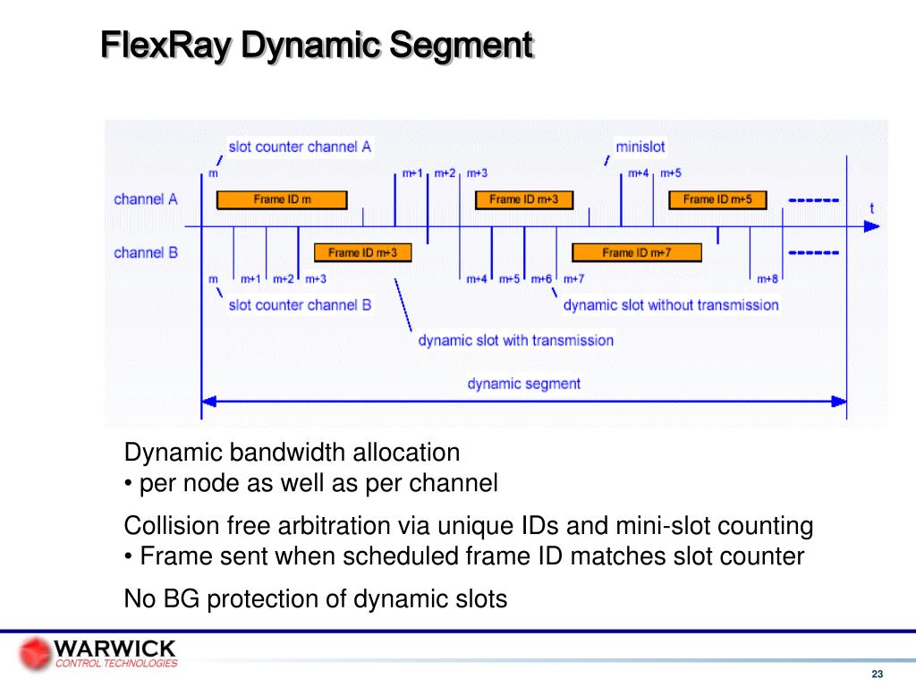
FlexRay: A Time-Triggered Protocol for Drive-by-Wire Applications Syed Masud Mahmud, Ph.D. Electrical and Computer Engg. Wayne State University Detroit MI 48202. Message transmission is followed by the channel idle delimiter, which consists of eleven bits — as in the static slot. It should be noted that per FlexRay specification a dynamic message must end precisely with the next possible action point.
“The FlexRay Communications System is a robust, scalable, deterministic, and fault-tolerant digital serial bus system designed for use in automotive applications.” (www.flexray.com)
In the following article you’ll find a possible solution for managing the communication between several nodes in a vehicle, using FlexRay. This solution has been provided for the System Architecture and Engineering course held at the Technikum Wien University of Applied Sciences.
Let’s start with a short description of our available hardware. The picture below shows an illustration of the system.
 There are five nodes in our system, running parallel and communicating with each other using FlexRay frames. Our job is to design the FlexRay cluster, and build error handling scenarios.System specification:
- Pedal node: each of the pedal nodes has to send the current pedal position to the calculation node.
- Calculation node: it has to calculate the motor speed that is to be set from the read in pedal positions. It is a must-have that both pedals have an impact on the motor speed.
- Motor node: this node reads in the motor speed from the calculation node and controls the motor.
- Control node: this node has to monitor the other four nodes and has to send a warning message to all nodes if one or more nodes are not functional. The warning message has to be handled on each node.
- Specifying the FlexRay configuration: e.g. length of one communication cycle, number of slots in one cycle.
- Specifying the FlexRay frames: e.g. data messages that the nodes exchange, synchronization frames
- Specifying application tasks: e.g. estimate WCET for every task, define offsets
FlexRay configuration
Number of FlexRay channels: 1.
In safety critical systems usually both FlexRay channels are used, as redundant channels. In this example, I’ve decided to only “use” one channel, for more simplitciy.
Cycle length: 5000 us
Number of static slots: 21
Static slot length: 200 us
Payload length of static slots: 4 byte
Dynamic segment – Minislot length: 6 us (the dynamic segment in this example is not used)
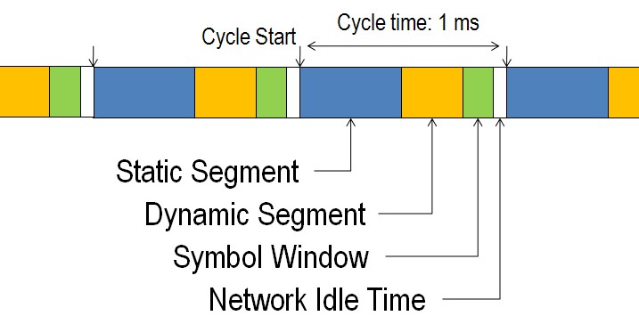
Network Idle Time: 200 us
FlexRay frames
On the following figure you can find the used FlexRay frames, together with slot numbers, frame producer node and frame consumer nodes.
Application Tasks
“A simple dispatcher runs on every node which provides an environment for the application. This dispatcher is synchronized with the FlexRay cycle and starts the different tasks at their pre-defined time. It cannot stop a task on its own so the developer has to assure that each task can finish its process before the next task should be started.” (DI Andreas Puhm)
Below you can find the WCET (worst-case execution time) estimation, which helps in the decision for different activation times of the tasks on one node and should prevent the case that one task misses its activation time because the previous task is still running (this has to be avoided at all costs).
Each node needs one SystemTask (WCET 500 us) and one or more application tasks.
Flexray Slot
The WCET for each task has been calculated using following algorithm: 100 us is needed to read or write one FlexRay slot. So the total time needed for one task is: (Nr. of frames) * 100 us + 100 us margin.
In this configuration, there is no separate task for sending the synchronization frames, so in our case Nr. of frames = Nr. of Data Frames + 1 SyncFrame. (If both FlexRay channels are used, the WCET time should be calculated with the formula: 2*Nr. of Frames + Margin)
In order to set the offsets for each task, it is easier to create a timeline first. After the timeline is created, the offset values can be easily read from the graphic.
Handling errors

Conclusions – Lessons learned
- design your system so that your well written, tested applications task could be used in as many cases as possible (reuse)
- an application task must be always scheduled to start only after all messages needed by the task are available
- avoid one servant – multiple masters configuration between application tasks. Slave tasks will not work as intended if they receive commands from multiple master processes
Note: the FlexRay cluster design provided in this article is not an optimized version!
The purpose of this test is to verify the integrity of the FlexRay networks by checking the mirror image nature of the signals and the coincidence of the edges.
How to perform the test
View connection guidance notes.
- Use manufacturer data to identify and access FlexRay high and FlexRay low circuits. (access is usually available at the multi-plug connector on components controlled by FlexRay, door locks, window motors etc.).
- Connect PicoScope Channel A to FlexRay high.
- Connect PicoScope Channel B to FlexRay low.
- Minimize the help page. You will see that PicoScope has displayed an example waveform and is preset to capture your waveform.
- Start the scope to see live data.
- Operate the system you have accessed.
- With your waveforms on screen stop the scope.
- Use the Waveform Buffer, Zoom and Measurements tools to examine your waveform.
Note
The BNC-to-4-mm cables that are used for normal signals are not suitable. For high-speed signals like those used on the FlexRay network, you must use high-speed probes.
Example waveform
Waveform notes
The above FlexRay waveform is a detail zoom of the FlexRay message and allows the individual state changes to be viewed. This enables the mirror image nature of the signals, and the coincidence of the edges to be verified.

Here we can see clearly that the signals are equal and opposite, and that they are of the same amplitude. The edges are clean and coincident with each other. This shows that the FlexRay network is enabling communication between the nodes and the FlexRay controller unit. This test effectively verifies the integrity of the bus at this point in the FlexRay network, and if a particular ECU (node) is not responding correctly, the fault is likely to be the ECU itself. The rest of the bus should work correctly.
Flexray Slot Id
It may be necessary to check the condition of the signals present at the connector of each of the ECUs on the FlexRay network as a final check. The data at each node will always be the same on the same bus. Remember that much of the data on the network is safety critical, so DO NOT use insulation piercing probes on FlexRay lines!
Further guidance
FlexRay is a fast, deterministic and fault-tolerant bus system for automotive use.
The FlexRay® protocol answers that demand with a high speed, deterministic and fault tolerant communications technology. Designed specifically for in-vehicle networking, FlexRay won't replace existing networks, but instead it will work in conjunction with already well-established systems, such as the controller area network (CAN), local interconnect network (LIN) and media oriented systems transport (MOST).
An in-vehicle network with FlexRay serving as the backbone provides determinism for engine control and fault tolerance for steer-by-wire, brake-by-wire and other advanced safety applications.
In FlexRay, the cycle period is divided into two parts: One static, for time-critical messages, and one dynamic, for less important messages. The static part is time-triggered whereas the dynamic part is event-triggered. For example, a node transmitting messages to the brakes would be in the static part whereas a node transmitting information to the audio system would be in the dynamic part.
FlexRay - compared to CAN - offers a significantly greater bandwidth of 10 Mbit/s.
Disclaimer
This help topic is subject to changes without notification. The information within is carefully checked and considered to be correct. This information is an example of our investigations and findings and is not a definitive procedure. Pico Technology accepts no responsibility for inaccuracies. Each vehicle may be different and require unique testsettings.

Suitable accessories
Help us improve our tests
We know that our PicoScope users are clever and creative and we’d love to receive your ideas for improvement on this test. Click the Add comment button to leave your feedback.
1 comment Add comment
I do not see the configuration of the high speed probe as being at all suitable for automotive use. This is a hand held lab scope probe, might be electrically suitable but not physically suitable